preaction system air leak fix is the first checkpoint buyers should lock before they approve a supplier, budget, or production slot. It’s 2 AM at a semiconductor fab in Hsinchu, and a 6-inch preaction valve is bleeding 2 psi every hour. The building engineer already has the diaphragm kit part number pulled up on his phone — he’s done this dance before. But many preaction system air leak fix jobs never touch the main diaphragm. The real culprit sits right on the pilot valve manifold: a loose 1/4-inch compression fitting that backed off during shipping vibration months ago and never got retorqued to 45 in-lbs. That’s not a parts problem. That’s a 10-minute wrench job.
The cost delta between replacing a valve assembly and retorquing six fittings is the difference between a scheduled maintenance window and an unplanned shutdown that triggers a false trip report to the AHJ. Field technicians often chase the diaphragm because that’s where the bubbles show up in the soap test. But pressure travels. A leak at the compression fitting migrates along the trim piping and escapes at the flange gasket, fooling the eye. Skip the isolation pressure test, and you’re ordering parts you don’t need while the system sits impaired. A 10°F overnight temperature drop can mimic a 2 psi leak all by itself — check the building’s temperature log before cracking open a single valve body.

The Six Common Air Leak Points on a Preaction Valve
Many leaking preaction valves have no manufacturing defect — only loose pilot manifold fittings from vibration in transit.
Ever asked a supplier why the preaction valve you just commissioned is losing 2 psi overnight and heard “that’s normal, just let it settle”? It’s not normal. Often, the leak has nothing to do with the main diaphragm or the valve body casting. The culprit is a handful of 1/4-inch compression fittings that backed off during freight. The fix takes ten minutes with a calibrated torque wrench and a 7/16-inch open-end wrench. Yet field technicians often burn half a shift chasing ghosts in the wrong part of the trim.
Apply leak detection solution to the six compression nuts on the pilot valve manifold. Bubbles forming at the ferrule-nut interface confirm the diagnosis. These 1/4-inch fittings carry supervised air pressure to the pressure switch and actuator. Thread engagement is shallow — only three to four full turns — so a quarter-turn of rotation can mean the difference between a 3 psi/hour leak and a tight system. The factory assembly torque specification is 45 in-lbs. Retorque every fitting on the manifold to that value using a calibrated inch-pound torque wrench. A crescent wrench won’t cut it; over-tightening collapses the ferrule and creates a permanent leak path that requires cutting the tubing and replacing the fitting.
A slow, steady pressure drop with no visible bubbles at any external fitting points to the diaphragm. The Buna-N diaphragm sits between the intermediate chamber and the valve body, clamped by a flange ring. Two things go wrong here. First, O-ring degradation from ozone exposure or oil carryover from a shop compressor feed. The rubber loses elasticity, develops micro-cracks, and can no longer maintain a seal under the 20–40 psi supervision pressure. Second, improper seating during initial assembly or after a field teardown. If the diaphragm is pinched between the flange faces or the bolt torque sequence was uneven, the leak path opens under thermal cycling. Isolate the intermediate chamber, pressurize to 40 psi, and watch a 10-minute log. A loss exceeding 1.0 psi with all external connections verified tight warrants pulling the diaphragm kit and inspecting the sealing surfaces for corrosion pitting.
A drip or audible hiss at the condensate drain is the easiest leak to find and the most commonly ignored. The drain valve sits at the low point of the trim, collecting condensation from air that enters the system during maintenance. Debris — pipe scale, excess thread sealant, dust — gets trapped on the seat, preventing a positive shutoff. Remove the drain valve, clean the seat with fine emery cloth, and inspect the ball or disc for wear. If the seat shows grooving or pitting, replace the drain valve. A five-dollar part left leaking wastes hours of diagnostic time and masks whether the system can actually pass a supervision test.
Air escaping from the pressure switch housing itself signals either a cracked boot or a loose threaded connection where the switch screws into the trim manifold. The rubber boot hardens over time, especially in dry-pipe cabinets exposed to ambient heat from nearby mechanical equipment. When the boot cracks, supervised air bypasses the diaphragm inside the switch and vents to atmosphere. Tighten the switch body into the port first — if the leak persists, replace the factory boot. This is a five-minute fix requiring pliers and a replacement boot, and skipping it is what turns a minor air loss into a false trip on a Friday night.
Apply leak detection solution to every NPT joint in the trim piping. Bubbles at these connections come from two root causes: thermal expansion cycles that loosen thread engagement over years of seasonal temperature swings, and low-quality thread sealant applied during original assembly. Here’s a hard rule field veterans learn the expensive way: PTFE tape is prohibited in preaction valve trim. Tape shreds migrate into the pilot valve manifold and pressure switch ports, causing intermittent blockages that are nearly impossible to diagnose without a full teardown. Use an anaerobic sealant like Loctite 567 on all threaded trim joints. Brush it on, assemble, and allow a 24-hour cure before pressurizing if ambient temperature is below 50°F.
A visible leak at the body split — where the upper and lower castings bolt together — points to gasket fatigue or corrosion pitting on the flange faces. This is the least common leak point, but it’s the one that triggers a replacement decision. Inspect the body flange surfaces once the valve is depressurized and split. If pitting exists, a new gasket alone won’t seal. The body casting is damaged beyond field repair. At that point, a full valve replacement is the only option that won’t fail again within a year.
How to Perform an Isolation Pressure Test in 15 Minutes
A 15-minute isolation test pinpoints the exact leak source, not just the symptom.
Before tearing into the diaphragm or ordering a full valve kit, isolate the trim from the system piping. This separates a false alarm from a genuine maintenance problem. The procedure uses the intermediate chamber test port standard on 2″ to 8″ preaction valves and takes exactly 15 minutes with nothing more than a gauge, soap solution, and a wrench.
Step 1: Close the air maintenance device valve and let the system stabilize for two minutes. Any lingering pressure fluctuations from the compressor cycle will settle, giving a clean baseline.
Step 2: Introduce air through the intermediate chamber test port until the gauge reads 45 psi ±1. Use a regulated nitrogen or dry air source. Shop air carries moisture and oil that can skew leak bubble tests later.
Step 3: Immediately close the test port isolation valve. This severs the valve trim assembly from the rest of the system piping, so any pressure drop you measure is happening inside the trim — not downstream in the sprinkler pipes.
Step 4: Monitor the gauge for 10 minutes. Record the reading at 2-minute intervals. A drop under 0.5 psi is normal and often traceable to temperature stabilization. Between 0.5 and 1 psi points to a minor leak — loose fittings or a drying O-ring. A drop of 1 to 3 psi signals moderate leakage, typically from several small leak points. Anything beyond 3 psi in 10 minutes is severe; shut down and pull the trim for bench inspection.
- Normal (<0.5 psi): Continue monitoring monthly. No action required.
- Minor (0.5–1 psi): Check all six common leak points with soap solution. Retorque fittings to 45 in-lbs.
- Moderate (1–3 psi): Test each fitting individually. Likely needs O-ring replacement or thread sealant.
- Severe (>3 psi): Isolate the valve immediately. Inspect diaphragm and body for damage. May require a new trim set.
Step 5: If the drop exceeds 0.5 psi, apply a thin soap solution to all six common leak points — start at the pilot valve manifold fittings. Air leaks often originate there, usually from 1/4″ compression fittings loosened by shipping vibration. A bubble at the pilot valve fitting confirms the culprit in seconds. Work outward from there: diaphragm flange edge, condensate drain, pressure switch port, threaded trim joints, and finally the main body gasket.
Record the pressure drop and isolate the bad component. A diaphragm kit covers the main flange seal; a cracked pilot valve fitting means replacement trim. Either way, the isolation test prevents replacing a healthy valve when a kit and a torque wrench would do the job.

Five Field Fixes That Don’t Require a Factory Overhaul
Many leaks are 10-minute torque fixes — no parts needed.
A common pattern: a technician orders a new diaphragm kit, but the actual leak is a backed‑off compression nut on the pilot manifold. Before spending money on parts or scheduling a shutdown, run through these five field procedures. Every one of them can be completed with the tools already in your service truck, and none requires an engineering change.
- Retorque Pilot Valve Fittings: Set a calibrated torque wrench to 45 inch‑pounds. Use a 7/16‑inch open‑end backup on the fitting body. Snug all six compression nuts on the pilot manifold — the vibration from ocean freight routinely loosens them below 20 inch‑pounds. Pressurize and check with soap solution. Average time: 10 minutes.
- Replace Pilot Valve O‑Rings: Isolate the pilot assembly and remove the actuator cap. Extract the old 2‑010 Buna‑N O‑rings with a brass pick. Wipe the groove clean, lubricate the new rings with silicone grease, and seat them without twisting. Re‑assemble and verify bubble‑tight seal at 40 psi. Average time: 15 minutes.
- Clean and Reseat the Condensate Drain Valve: Close the upstream isolation valve. Remove the drain valve cartridge and inspect the seat. Polish the seating surface with fine emery cloth, working in a circular motion. If the seat shows deep pitting, swap the cartridge — a drain drip will mimic a system leak and trigger supervisory alarms. Average time: 20 minutes.
- Apply Anaerobic Thread Sealant to Trim Joints: PTFE tape has no place on preaction trim. Shredded tape migrates into the pilot port and blocks the orifice. Break the leaking joint, clean both male and female threads with solvent, and apply a thin layer of Loctite 567 anaerobic sealant. Reassemble and allow 15 minutes cure before pressurizing. Average time: 15 minutes per joint.
- Replace a Cracked Pressure Switch Boot: If the rubber boot on the supervision pressure switch shows cracking or hardening, air will track through the housing. Pop off the damaged boot, push on an OEM replacement, and secure with the spring clip. No thread sealant or tools beyond needle‑nose pliers are required. Average time: 5 minutes.
When to Order a Factory Diaphragm Kit vs. a Full Valve Replacement
Many valves flagged for replacement only need a diaphragm kit.
Did the service contractor actually put a bore scope on the valve body before quoting a full replacement?
The decision hinge is not price. It is whether the valve body sealing surface still meets the quality tolerance needed to hold a Buna-N diaphragm under 40 psi supervision pressure. Here is the split test.
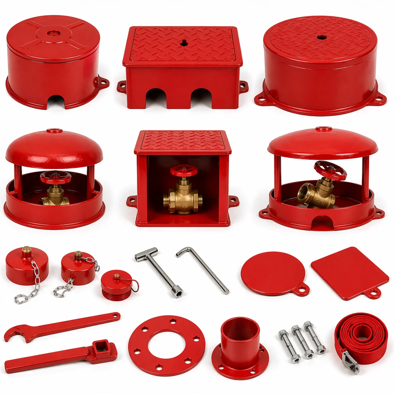
- Diaphragm Kit — Go This Route When:: Leak is isolated to the main diaphragm flange. Soap test confirms bubbles only at the flange edge, not at trim joints or body casting. Valve body shows no visible pitting on the sealing land — surface oxidation is acceptable, but any crater deeper than 0.005″ will prevent a seal. Trim manifold passes a 45 in-lbs retorque without stripping. Valve has under 15 years of service and no history of water hammer events.
- Full Valve Replacement — Pull the Trigger When:: Body casting shows pitting, especially around the intermediate chamber test port or drain boss — these areas trap moisture and corrode from the inside out. Trim manifold has a stripped thread or a crack at any compression fitting boss. Multiple leak points appear simultaneously — diaphragm flange AND pressure switch port AND a trim joint all leaking at once signals systemic degradation, not a single-point failure. Valve has exceeded 15 years of service in a space with temperature swings exceeding 30°F seasonally. Previous repair attempts failed within 6 months.
- The Body Inspection Before You Order:: Before ordering anything, pull the diaphragm cover. Clean the sealing land with a Scotch-Brite pad. Run a fingertip across the surface. If it catches on a pit, order the full valve. If it is smooth with minor discoloration, the diaphragm kit will seal. A 10x jeweler’s loupe makes the call obvious. This inspection takes 15 minutes and is the difference between a kit repair and a full replacement.
One more variable that procurement checklists often miss: FOB pricing on full replacement valves can change depending on whether the order includes the trim kit as a pre-assembled unit or as separate SKUs. If the supplier ships the valve body and trim in two cartons for on-site assembly, the freight class changes. Ask for the assembled weight and dims on the quote.
Sample approval discipline applies here too. If ordering diaphragm kits in bulk — say, stocking 20 kits for a facility with 40 preaction valves — request a single pre-production sample from the lot. Install it on one valve. Run a 48-hour supervision pressure test at 40 psi. Log the pressure every 4 hours. If the drop stays under 0.5 psi over 48 hours, release the balance. If it does not, reject the lot before opening the remaining 19 kits. This is not protocol in many maintenance shops. It should be.
Conclusion
Before ordering a single part, run these three checks. One: did a calibrated torque wrench hit every 1/4″ compression fitting at 45 in-lbs? Many air leak complaints trace back to fittings that backed off during shipping — a ten-minute fix with zero parts cost. Two: can you rule out temperature drift? A 10°F ambient drop shaves roughly 2 psi off the gauge and mimics a real leak convincingly enough to waste an afternoon. Three: is the valve body clean of pitting and corrosion? If the leak isolates to the diaphragm flange and the body is sound, a diaphragm kit gets it done. A corroded body means the full valve replacement is the only honest call.
When replacement parts are needed, sourcing from the original manufacturer cuts out fitment guesswork and keeps warranty claims straightforward. Review the preaction valve and diaphragm kit specifications on the Fire Sprinklers & Alarm Valves page to verify part numbers against your system configuration before ordering.
Frequently Asked Questions
What psi should a preaction system hold?
Preaction systems typically hold 40 psi supervisory air pressure, though some nameplates specify 30–45 psi. NFPA 13 requires supervision to alarm on a 10 psi loss, so your setpoint must. Check the valve nameplate for the factory-set pressure before making any adjustment.
Can I use compressed air from a shop compressor?
No, shop compressors inject oil and moisture that degrade pneumatic trim and accelerate false trips. Always supply clean, dry air from an oil-free fire protection. A dedicated compressor like those cross-referenced by C-Aire removes moisture and oil before it reaches the valve.
How often should I test the air supervision pressure?
NFPA 25 mandates quarterly functional testing of the air supervision device to confirm alarm activation at the proper pressure. Between tests, check the gauge weekly to spot trends. Log daily pressure readings during cold snaps to separate thermal effects from real leaks.
Why does the pressure drop when it gets cold?
Air contracts as temperature falls; a 10°F drop can reduce pressure by about 2 psi, mimicking a small leak. Let the system stabilize at the ambient condition before assuming a mechanical fault. Always record both gauge pressure and ambient temperature when troubleshooting.